Table of Contents
Modifying A5/A3S with an Automatic Bed Levelling Probe
Several types of probes are available:
- Optical / IR probes (as we're discussing here)
- BLtouch (great, more complex installation, but easier to break. Clones are cheaper but very poor reliability)
- Inductive probes (not recommended for the A5 as the aluminium plate is too thin, not covered on this site)
Most people who have chosen to add a bed levelling probe to their printer have used an IR probe. This probe typically replaces the connection to the Z-min endstop.
Please Note: The ceramic coating on the original bed has a pattern that can cause inaccurate measurements when using an IR / optical probe due to the inherrant uneven nature of the surface coating. If you are using the original coated glass with an IR/Optical probe, it is suggested that you turn the glass plate upside down, and then add some black mat material underneath the glass or paint it to solve the issue. Standard deviation with this sensor on a plain glass sheet shows a 0.2mm deviation, which is 1 layer height!
Initial Considerations
From my testing and learning as a complete newbie to this whole automatic bed levelling jibberish, three things have become vitally important, you need to pay attention to all three for the system to work.
Levelling the X Axis
First, we need be sure that your X axis carriage is actually level. As the A5 uses two steppers and two threaded rods to hold the carriage in place, this can get out of alignment so one side can be higher than than the other.
- To correct/check this, move the Z axis as high as it will go and use come calipers to measure the distance from the bottom rail to the frame, this should be identical.
- If the measurements are out, turn the printer off and use your hand to manually move the threaded rod couplers to move one side up or down. It doesn't matter what height they actually are, just make sure they're the same!
Print Surface
More detail on this is below, but the quick detail is the A5's glass bed is NOT suitable for an IR probe on its own. Glass is a poor reflector of IR light and the Black diamond build surface interferes with the reflection pattern. I would HEAVILLY advise you but a good surface such as PrintBite, I have had amazing consistence with this.
Z Axis Friction
Whatever lubricant JGAurora use on the threaded rods lifting the Z axis is utter garbage. After only 3 weeks, the stuff on my rods had turned all sticky meaning the tiny movements the printer has to do were not being performed correctly. This manifested itself in what sounded like a grinding noise coming from both of the Z axis steppers. I would recommend checking yours moves freely, and if youre concerned, clean the old stuff off and replace it with something like Machine Oil, or your preferred choice of lubricant.
The reason for this is if the motors turn enough to say, raise the bed 1mm, but for 50% of the movement, they stall because of the friction, your next probe measurement is going to be way off. I had probes that were (apparently) 44mm offset from probe point 1, that's utter madness and was caused by the motors stalling for a portion of their move on every single measurement point. Lube up your rods people!
IR Probe Bed Surface Compatibility
In order for this to work, the sensor needs to “see” the reflection of the IR beam from the top surface of the bed. There is a potential problem when the sensor is used with a transparent bed material that reflects infrared light weakly and there is a surface below the transparent material that reflects IR much more strongly.
Glass (with or without coatings such as hairspray, PVA or Kapton tape): Works as-is if placed directly on a PCB bed heater or other surface that does not reflect strongly. Coatings on the glass such as the Black Diamond coating affect the trigger height hugely so its advised to flip the glass upside down, paint it and install a new surface like PrintBite.
PEI: NOT compatible
BuildTak: The dark grey variant works well with the sensor. The white variant is untested, but it should work too.
PrintBite: Early samples were found to be opaque to IR (so these work OK), but more recent samples are transparent to IR. This means that it needs to be painted black on the underside in order to work well with the IR sensor. However, this is not practical if the PrintBite sheet has the adhesive already attached.On the A5, its suggested to follow the advice as per glass. Install/paint the surface between the PrintBite and the glass bed.
Anodised aluminium, with or without PEI coating: suitable if the finish is matt or semi-matt.
Bright Aluminium: NOT compatible
Mirror: NOT compatible
Other/Not Listed: You will have to check yourself if your surface is transparent to IR light, an easy way to do this is with a standard TV remote control.Place your hand in front of the remote control to block the infrared signal and verify that the remote control no longer controls the TV. (Don’t wrap your hand over the front of the remote control). If the remote control still works, you may be too near the TV, you may need to back away and try blocking again. In that case, you'll need to repeat step 1 to verify the remote control works at the farther distance when it isn’t blocked.
Place the build platform you want to test directly in front of the remote control and test to see if the remote control can still control the TV. If the remote control no longer works, then the object either absorbs, redirects, or otherwise blocks infrared and your IR sensor will be able to “see” the build surface. If the remote control still works, then at least some infrared is passing through and you may have trigger issues without applying some remedial method such as painting the underside as detailed above..
How-To Install IR Probe
Steve Wagg has put together an EXCELLENT guide on performing this mod on thingiverse. Steve has a modified version of the community firmware that is ready to go, configured for use with the IR sensor plugged into the Z-min socket.
If, like me you have the TMC2130 steppers drivers, or other hardware mods that require firmware edits, or youre just the type that likes to do these things manually, then stay here and follow all the info below.
Full Firmware & Hardware Modification Guide
What to Buy?
Infrared sensor - IR Sensor Link
Mounting Bracket (Print this before you do the mods!) - Sensor Bracket Link
3 wire servo extension lead (2 x 1m in length) - Servo Extension Link Link
Or, you'll need you own wire and either DuPont connectors or a 3pin JST Plug and tools to wire this up.
Firmware Edits
Since this is what frightens most people, lets start here.
- Grab a fresh copy of Marlin 1.1.8c from Sams repository http://sampin.ch/A5-firmware
- At the time of writing, you want the file “JG A5 Custom Main Marlin 1.1.8C.zip”. The newer 1.1.9 beta is NOT recommended, development hasn't finished on that version yet (14/03/2019)
- Extract the ZIP file and open up the Configuration.h file in Notepad or Arduino IDE 1.8.5 and make the following edits;
Line 517
Original
#define Z_MIN_ENDSTOP_INVERTING true
Change To
#define Z_MIN_ENDSTOP_INVERTING false
Line 649
Original
//#define FIX_MOUNTED_PROBE
Change To
#define FIX_MOUNTED_PROBE
Line 706-708
Original
#define X_PROBE_OFFSET_FROM_EXTRUDER 10  // X offset: -left  +right  [of the nozzle]
#define Y_PROBE_OFFSET_FROM_EXTRUDER 10  // Y offset: -front +behind [the nozzle]
#define Z_PROBE_OFFSET_FROM_EXTRUDER 0   // Z offset: -below +above  [the nozzle]
Change To
#define X_PROBE_OFFSET_FROM_EXTRUDER 6  // X offset: -left  +right  [of the nozzle]
#define Y_PROBE_OFFSET_FROM_EXTRUDER -30  // Y offset: -front +behind [the nozzle]
#define Z_PROBE_OFFSET_FROM_EXTRUDER -1.1   // Z offset: -below +above  [the nozzle]
OPTIONAL - SLOWS DOWN PROBES FOR MORE ACCURACY
Line 717
Original
#define Z_PROBE_SPEED_SLOW (Z_PROBE_SPEED_FAST / 2)
Change To
#define Z_PROBE_SPEED_SLOW (Z_PROBE_SPEED_FAST / 4)
OPTIONAL - SLOWS DOWN PROBES FOR MORE ACCURACY
Line 722
Original
//#define MULTIPLE_PROBING 2
Change To
#define MULTIPLE_PROBING 3
Line 803-804
Original
#define X_BED_SIZE 305
#define Y_BED_SIZE 305
Change To
#define X_BED_SIZE 310
#define Y_BED_SIZE 310
Line 894
Original
//#define AUTO_BED_LEVELING_BILINEAR
Change To
#define AUTO_BED_LEVELING_BILINEAR
Line 896
Original
#define MESH_BED_LEVELING
Change To
//#define MESH_BED_LEVELING
Line 937-940
Original
#define LEFT_PROBE_BED_POSITION 15
#define RIGHT_PROBE_BED_POSITION 170
#define FRONT_PROBE_BED_POSITION 20
#define BACK_PROBE_BED_POSITION 170
Change To
#define LEFT_PROBE_BED_POSITION 10
#define RIGHT_PROBE_BED_POSITION 295
#define FRONT_PROBE_BED_POSITION 25
#define BACK_PROBE_BED_POSITION 280
Line 1017
Original
#define LCD_BED_LEVELING
Change to
//#define LCD_BED_LEVELING
Line 1054
Original
//#define Z_SAFE_HOMING
Change To
#define Z_SAFE_HOMING
Line 1490
Original
//#define REPRAP_DISCOUNT_SMART_CONTROLLER
Change To
#define REPRAP_DISCOUNT_SMART_CONTROLLER
Line 1504
Original
#define REPRAP_DISCOUNT_FULL_GRAPHIC_SMART_CONTROLLER
Change To
//#define REPRAP_DISCOUNT_FULL_GRAPHIC_SMART_CONTROLLER
OK, still with me? Next, just follows Sams guide for flashing this firmware to your A5, but don't try any test prints yet, just do the flash, then shut it down again! https://jgaurorawiki.com/a5/firmware
The Glass Bed
The original developer of these mini IR boards has specifically said he designed it to work on glass, which it does but I guess since the original design with ever smaller layer heights on todays 3D printers, the deviation is just unacceptable. Youtuber Thomas Sanladerer ran tests on this sensor and found a deviation of 20 micros, or 0.02mm which is one layer height Link to His Video on plain glass, community testing has resulted in WILDLY inaccurate heights, basically, do NOT do this if you plan to use the standard Black Diamond glass as your print surface, it just wont work.
The best way to fix this is to paint the glass to give the IR beam a better material to bounce back from. The exact colour of the paint doesn't really matter, but the even-ness of the coats do. Even a small hair will affect your trigger distances!
- Remove the four bed levelling screws and unplug the bed connector
- Remove the metal clips holding the glass bed to the metal hot plate.
- NOTE: Older beds that don't have the metal clips are usually stuck with adhesive. You won't be able to remove this and clean the bed enough to not affect your trigger distances, you're better off buying a new glass bed and build plate, but you're welcome to try.
- Flip the glass over so you're painting the clear side, not the Black Diamond coated side.
- Clean the glass with something (IPA Alcohol or paint prep fluid) and then spray on a couple of coats of All Surface Primer, again, colour isn't important but i used grey.
- Once you have a few layers of primer, put on 2-3 light coats of paint, i used black. Ensure you have a good solid colour and even coverage, then allow this to harden overnight.
- Since a perfect level height is important, we need to sand this now, this will remove any hairs etc that landed in your paint. Sand first with 600 grit sandpaper using water and washing up soap as a lubricant until the bed feels smooth and is matte. Don't use a lot of pressure as you don't want to burn through the paint to the primer. Were just worried about removing hairs and any tiny imperfections.
- Clean the bed again and apply one final coat of paint. Again, leave to dry overnight or for a few hours at the very least.
- I then sanded the entire bed with 2000 grit sandpaper to end up with a perfectly smooth matte finish, this step may be unrequired though.
As mentioned above, this doesn't really work on the glass bed so I'm also going to be adding a PrintBite build surface rather than use the Black Diamond. I've had really good experience with this over the years, works really well for PLA, ABS, PETG and loads of others. The final sandwich of layers in my case would be;
Heated Plate > Glass Bed (With Black Diamond coating facing down and painted surface facing up) > Print Bite build surface (stuck to the new painted glass).
Hardware Changes
- If you've purchased a pre-made cable, you can skip these steps;
- You need to now create a wire using the included “Cable Kit” and your own wire.
- Cut 3 lengths of wire at 1.5 metres and strip the ends.
- Insert one end of the bare wire into the small terminal pin/clamp things that come in the cable kit with the IR sensor. You should have around a 1mm section of the cable sheath right at the end of the gripper section.
- Use a proper terminal crimper, or if your careful use some small needle nose plyers to crimp the terminals around the wire, give the wire a tug to ensure its held in place.
- Insert the crimped terminal into the black plug, you should hear a small click once the terminal is inserted properly.
- Solder the bare ends of the wire to the pins on your sensor, the plug end gets dealt with later in the guide.
- Unscrew the Z axis end stop, you will not be using this any longer. You can either totally remove it, or just tuck it back inside the printer for safe storage.
- Unscrew the two screws on the vanity plate covering the X Axis carriage. These can be found on the left and right of the metal plate. You will not be re-fitting this plate.
- Unscrew the two screws on the X axis itself directly in front of you and then re-attach with the 3d printed bracket from the Thingiverse link at the top of this page. You will need slightly longer M3 screws to do this.
- Attach the IR sensor to the two remaining holes on the bracket.
- Route the 3 wires up, through the plastic tubing and all the way through the access hole on the right side of the machine where there will already be wires coming from.
- Unscrew the 5 screws holding the Y axis, and build plate so that you can remove the top cover of the machine and see the wires and PCB's inside. You dont need to remove the bed to do this.
- Locate your Z Axis End stop plug. This will be a green connector with a Blue and then a red one above it. Right above those will be an empty stepper driver slot. Unplug the old Z axis end stop and plug in your new one in its place.
- If you made your own cable rather than buying a pre-made one, you will either have to use DuPont connectors here, or wire this up properly with a 3 pin JST Connector.
- Make sure the cable is inserted the right way! From the top down, the wire order is VCC, GND and Signal.
- Route all the wires properly and then do up the whole case.
Setup and Testing
Now the hard parts are done, you need to complete the setup of the IR sensor and do some testing, so lets continue.
- Turn on the printer and using the LCD or a GCODE console such as Pronterface, issue a G28 or push the home all axis button on the LCD, otherwise the axis don't respond!
- Use the LCD in the MOVE menu and Move Z down slowly (0.01mm steps) until the probe triggers. This is when the red LED light comes on.
- Take the current Z value on the printers LCD screen and negate it. (so a value shown of 1.6 becomes -1.6), this is the offset between your print Nozzle and the sensor height.
- My Screen showed 1.6mm, I perfonally found I needed to add 0.2mm onto this, so my final value became -1.8
- If you want to lower the head by 0.02mm then you would issue the command “M851 Z-1.80” or to raise it by 0.02mm, its “M851 Z-1.4”. Yes, INCREASING the number LOWERS the head, backwards to what you'd think logically, but were using a - sign before it, so the logic is correct. Issue a M500 command to save this value in the EEPROM once you've figured out what it is. In my case, a value of -1.80 works well.
- Next, do a bed level using the LCD and the print bed levelling knobs so that the bed is as level as you can get it using this method, basically proceed to set the correct 0.2mm layer height pretending as if you don't have an IR sensor.
Now that you have an IR probe and a nice level bed, you need to be sure that before every print, you re-level the bed, but this time we can use the new probe to do that!
G29 is the GCODE to issue a level bed routine. You can run this now I guess to see it working, but in reality, all you need to do is add the following lines AFTER your initial G28 home command in your slicing software.
NOTE: Remember, any G28 Home command after this script will disable UBL again, so avoid placing G28's after this script.
G28		; Home All Axis
G29 P1 		; Mesh Probe Bed
M500		; Save To EEPROM
M420 S1		; Activate Mesh
And your done! From now on, the printhead will perform an automatic mesh bed level using the IR probe before every single print.
In standard probing mode, This adds about 30 seconds to your print time and ensures that crucial first layer goes down perfect every time!
If you also performed the ultra slow mods to get a better probe height, this takes a few minutes per probe cycle. Since we've saved the mesh to the EEPROM, you may wish to do this mesh periodically and just use the below as your start-up commands since we can call the mesh data back from EEPROM.
G28		; Home All Axis
M420 S1		; Activate Mesh
Useful Mesh Bed Levelling Commands
G29 - Issue this command to probe the bed and create a mesh using the IR probe
G29 Q - Issue this command to check if mesh bed levelling is enabled
M420 V - Issue this command to view the current mesh data (useful for comparing results)
M500 - Save the current mesh data to EEPROM
M503 - Show the current data in the EEPROM
M420 S1 - Activate the mesh bed levelling data in the print job
Wiring Photos
Hotend Sensor Wiring

Motherboard Sensor Wiring
NOTE: This is Sams photo, he left his end stop microswitch connected. If your following this guide properly, you should remove it and plug your IR sensor into its port, NOT the one sam has shown here, its still helpful photo as its the green connector just next to it.

Testing
You can test your ends top function using Pronterface, and entering gcode M119. This will report the status of all the endstops. You can put your finger under the sensor to trigger it, and then run M119 to see if the change in status is reported.
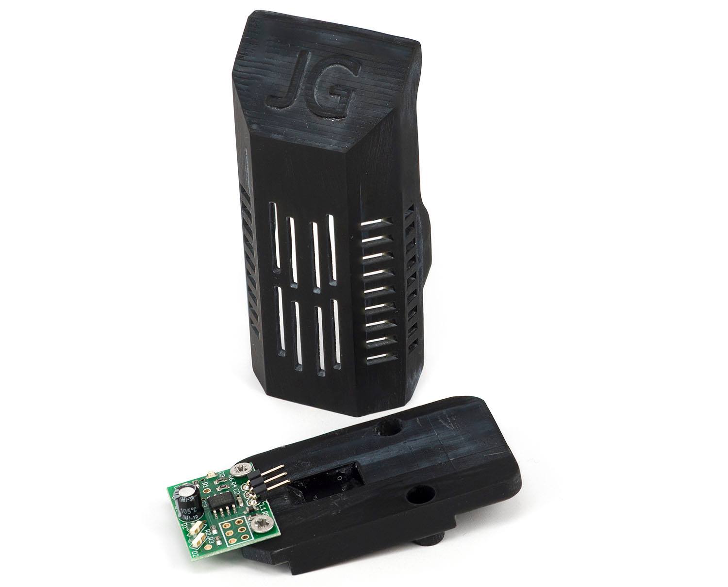 Photo credit: Marcus Harrysson on Facebook
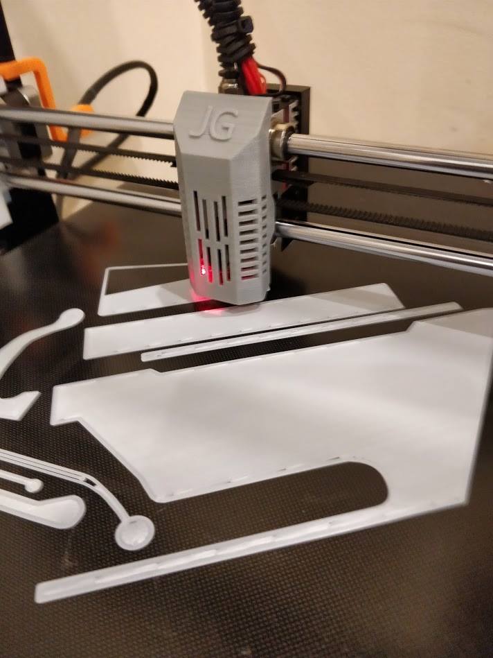 Photo credit: Steve Wagg on Facebook