Table of Contents
Programmable Power Supply Control
Author: AETEK
The changes shown here require knowledge in the field of Arduino, Marlin firmware and electrical engineering and can overwhelm normal users. Also, I would like to point out possible dangers that exist in certain interventions. All adjustments have been checked for function.
Difficulty: Professional or Electrician (No more warnings. Professionals know when to unplug the mains)
What is this about?
The following changes to the JGAURORA 3D printer have the goal to control the main power supply of the A5 via GCODES. Then it is possible to turn off the printer intelligently. Also, you can simply program that the A5 shuts itself off after the end of the print and the cooldown of the hot end. It is also possible to program the printer to turn itself off after a programmable period of inactivity. If the Marlin firmware detects hardware errors, then Marlin can also disconnect the A5 from the mains.
You should turn off the A5 after printing, after the Hotend has cooled to about 50 ° C. If you do not pay attention to this, then the filament can melt in the heat sink and harden on cooling. It forms a filament graft. The path to the nozzle is blocked. On the one hand you always have to think about it, on the other hand it is boring to wait until the hotend cools down. The A5 has a small computer and temperature sensor. With the resources available, this task can be done by the A5 itself.
- Please follow the sequence of work steps during construction.
- Use exactly the electronic parts mentioned. Other parts could cause damage to the motherboard.
- The circuit was calculated and the results verified with the meter.
Required Electrical Parts
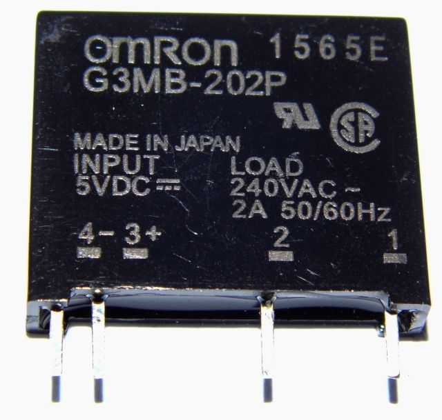
- 1 x Solid State Relay Omron G3MB-202P
- 1 x Low Current LED 5mm red 2mA
- 1 x Female Pin Header 2.54mm, 3 Pins
- Some cable and heat shrink
The Solid State Relay is cheap to buy on Ebay. One piece can be bought from $0.99 USD. From two pieces you get the parts even cheaper. Please only buy the original quality brand product from Omron. Just search for G3MB-202P. If the listing is correct, then the part must be designed for 5 volts. Attention, there are also variants with other voltages. The Solid State Relay is also available as a module with a printed circuit board. This version is unsuitable for this application.
The professional will most likely have the remaining parts in the tinker box anyway.
Build The Circuit Part 1
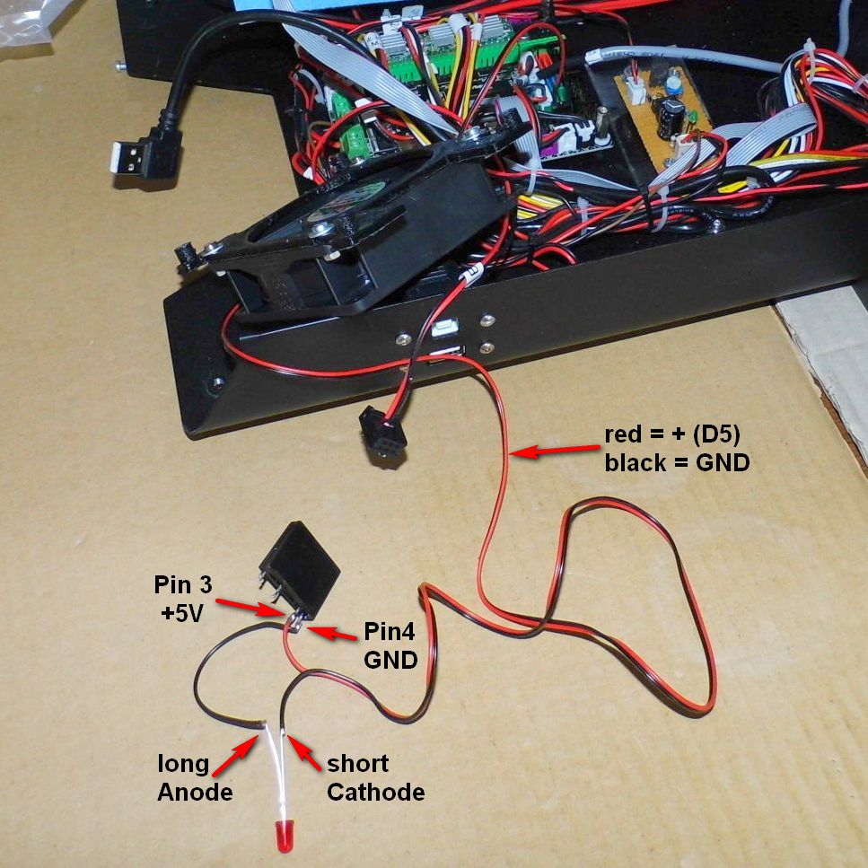
The first part of the circuit is temporarily set up for testing purposes.
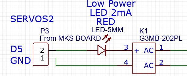
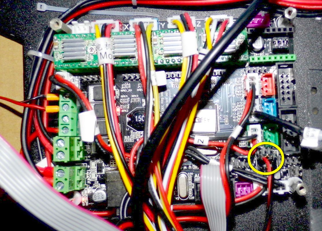
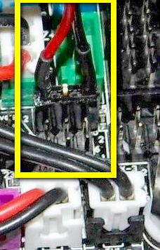
The female pin header is connected to the MKS GEN_L 1.0 mainboard.
The plug belongs to the SERVOS2 block (2nd from the top). See photos. Please note the polarity
The middle pin of the female pin header is not used and can be cut off.
Do the first test
For this test, the A5 does not need to be assembled. It can stay open.
Please place the provisional circuit outside the metal chasis (see photo) to avoid short circuits.
- Insert mains plug.
- Power on the printer and wait 10 seconds.
- The red LED of the test circuit should not light up.
- Now power off the printer and unplug the power cord.
Customize the Marlin firmware
In the Arduino IDE open the A5 Custom Community Firmware (see article here in WIKI).
The following adjustments are made in the “Configuration.h” file:
- Search for: #define POWER_SUPPLY
- Replace this line with this version: #define POWER_SUPPLY 2
In the file “pins_RAMPS.h” the following adjustments are made:
- Search for: #define PS_ON_PIN
- Replace this line with this version: #define PS_ON_PIN 5
Then upload the changed firmware to the A5 (instructions here in the WIKI).
Do the second test
For this test, the A5 does not need to be assembled. It can stay open.
Please place the provisional circuit outside the metal chasis (see photo) to avoid short circuits.
- Insert mains plug.
- Power on the printer and wait 10 seconds.
- The red LED of the test circuit should light up and stay on.
- Now power off the printer and unplug the power cord.
Mechanical Work
Required Mechanical Parts
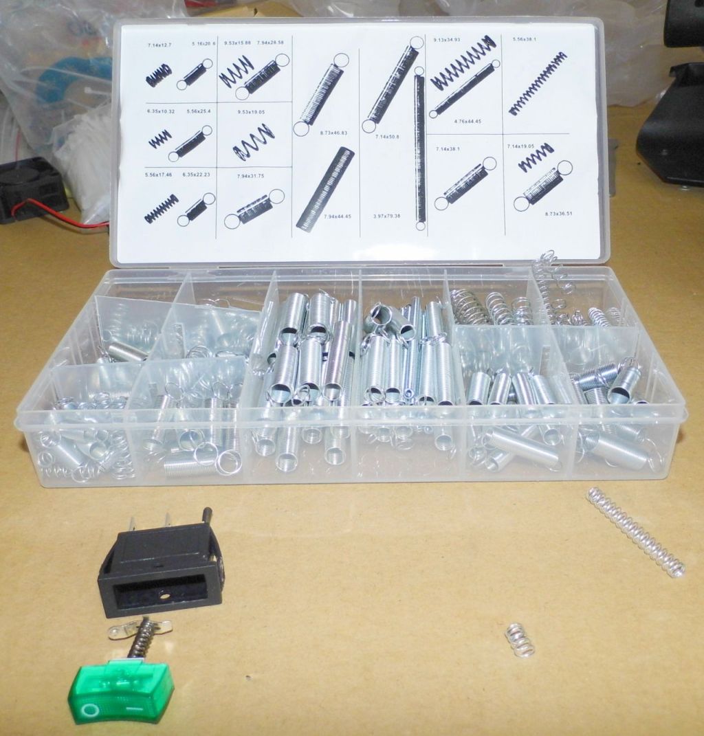
- Some different springs
For the conversion of the A5 a momentary switch in the dimensions 30 x 11mm is needed. I have already seen momentary switches with these dimensions. However, they are rare and usually difficult to obtain.
Now there are two possibilities:
- You get a momentary switch in the right size. (Good luck with your search).
- Convert the existing switch to a momentary switch.
Convert the existing switch to a momentary switch
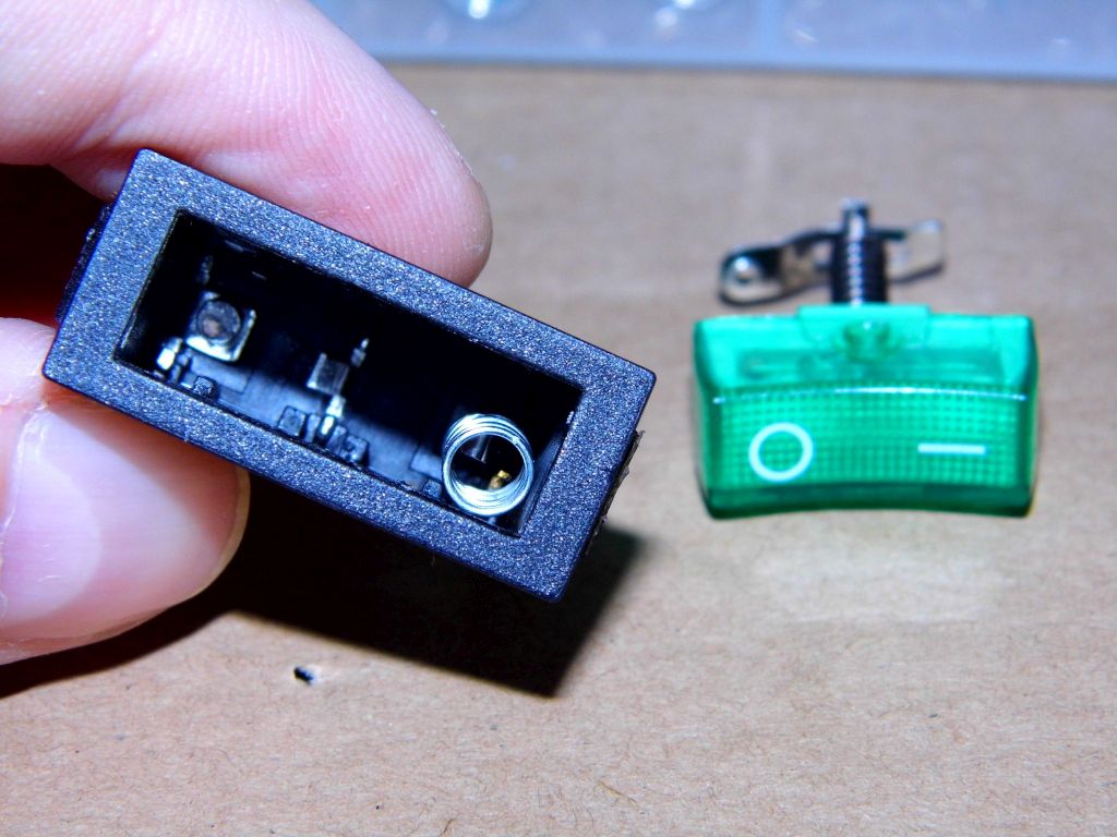
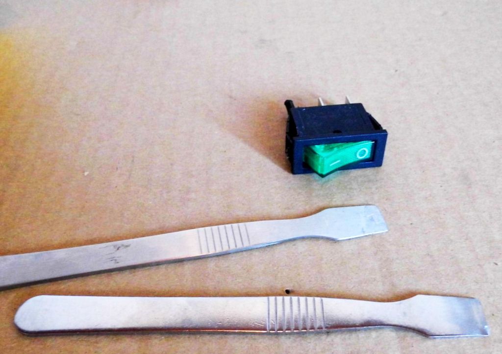
You need patience for a successful switch conversion. The work requires skilled craftsmanship and the testing of various spring combinations. First remove the switch from the case and then open it. The green rocker is held by two plastic nipples. As a suitable tool for opening Spudgers have proven. These tools are normally used to open tablet computers and smart phones.
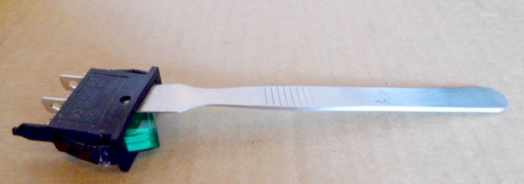
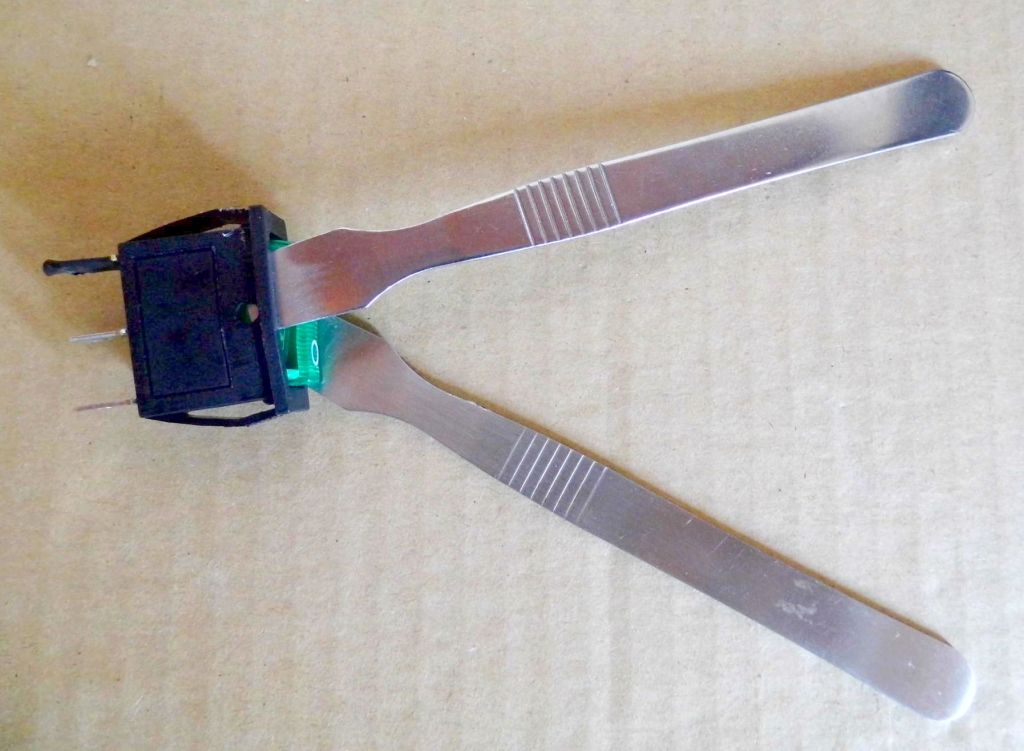
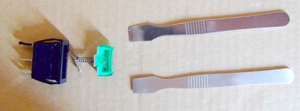
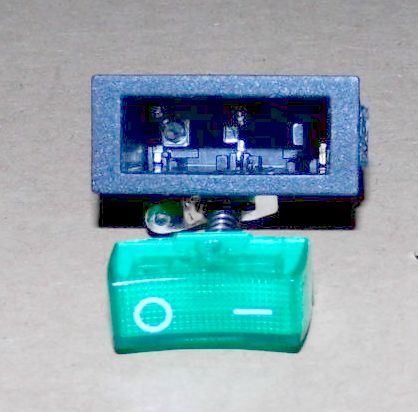
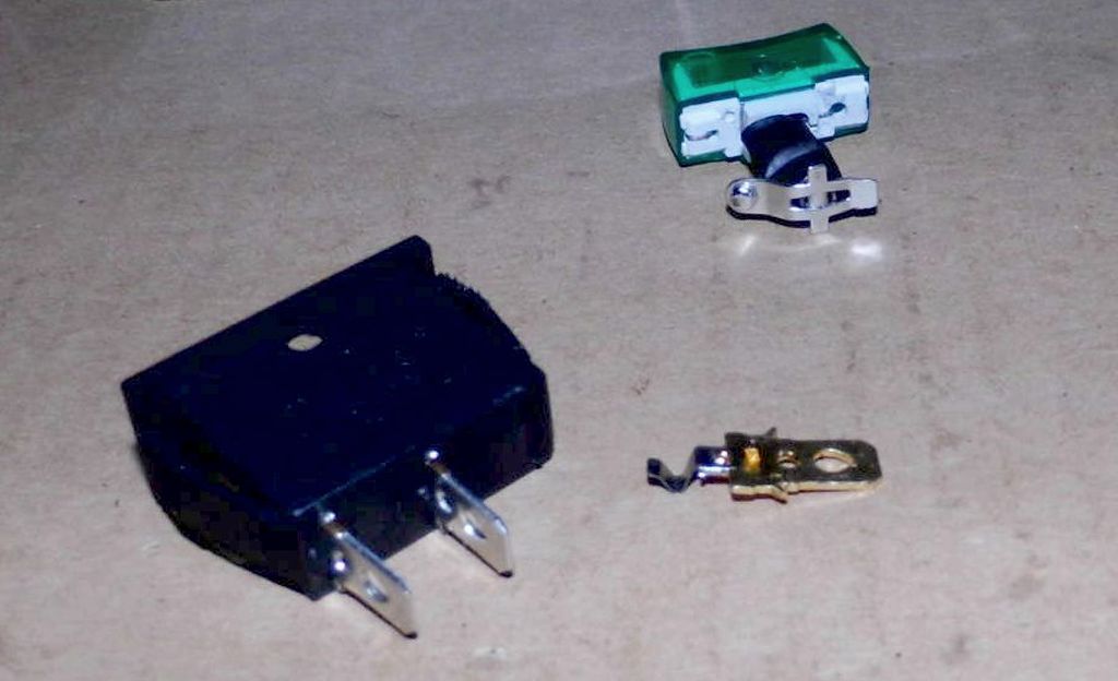 The work is fumbling. After some time, I decided to remove the unused contact. This gives more space for the installation of a spring. The spring should bring the rocker and the contact in the normal state (normally open). If you press the rocker switch to the ON position, the contact is closed until you remove the finger from the rocker. Then the built-in spring automatically moves the switch back to the off position. This then gives the momentary function (as with a doorbell).
Assembling the new Momentary Switch is not easy. There are now two springs in the housing, both of which must be at a certain point so that the function is given as desired. Tests have to be done after assembling the momentary switch.
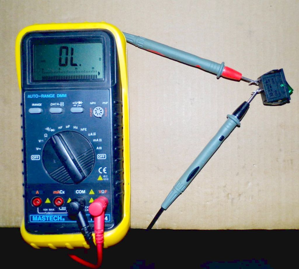
- Is the contact open while idle?
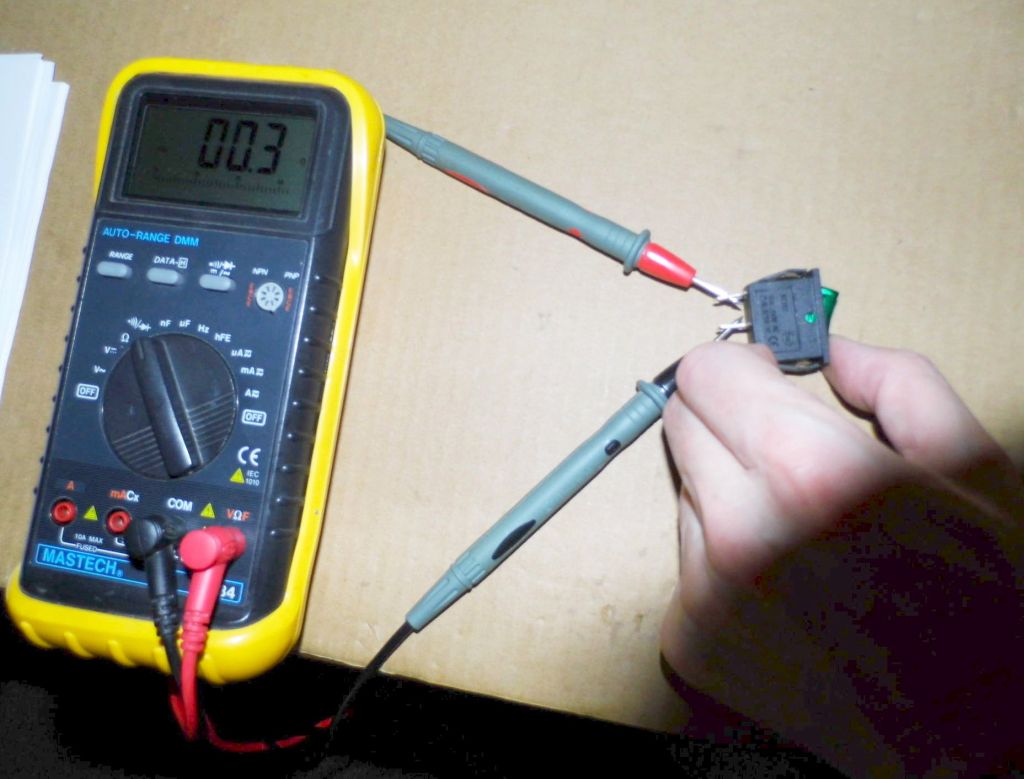
- Is the contact closed when pressed?
- Does everything work properly?
To do this, press the rocker repeatedly with the continuity tester connected and let go of the rocker. If this works more than 30 times in a row you can assume that everything is ok. If it does not work reliably, try different springs again and again until it works. That takes time and patience.
Build The Circuit Part 2
After this trip and the training of patience and the acquaintance with various springs, it continues with the electrical part of the project.
The provisional circuit is now removed. To do this, desolder the solid state relay and the red LED off the cable.
Here is the complete project schematic:
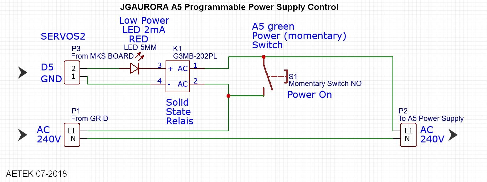
I had developed a complex special housing for the momentary switch and the solid state relay, in which the circuit should find its place. This would look like this:
Electrically everything worked wonderfully. Unfortunately I noticed a problem after assembling the A5. The measurement of the available space above the momentary switch upper edge was wrong. The Y-gantry does not have enough room to move because the housing of the momentary switch was too high.
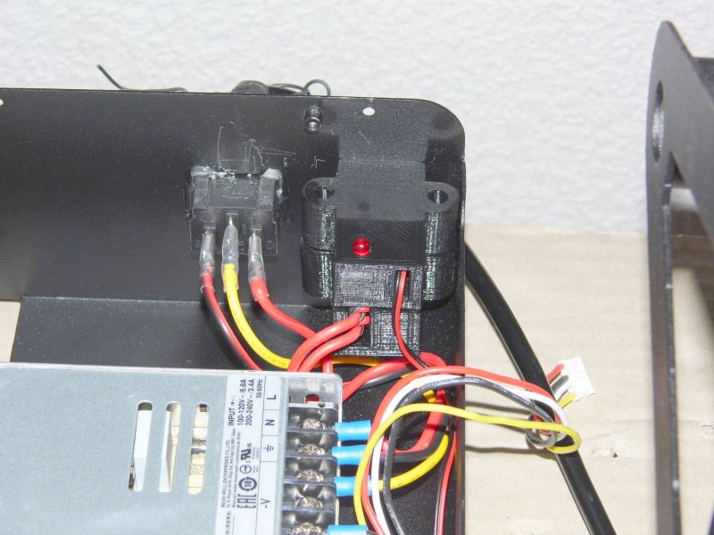
Because I wanted to get ahead with the project, I decided to continue without the switch housing. All parts are isolated from touch. If you like, you can develop a new switch housing or make it more beautiful.
To complete the circuit, some cable connections still need to be added. Following are some photos on which you can see the connections well. If something should be unclear, it may help to look at the wiring diagram.
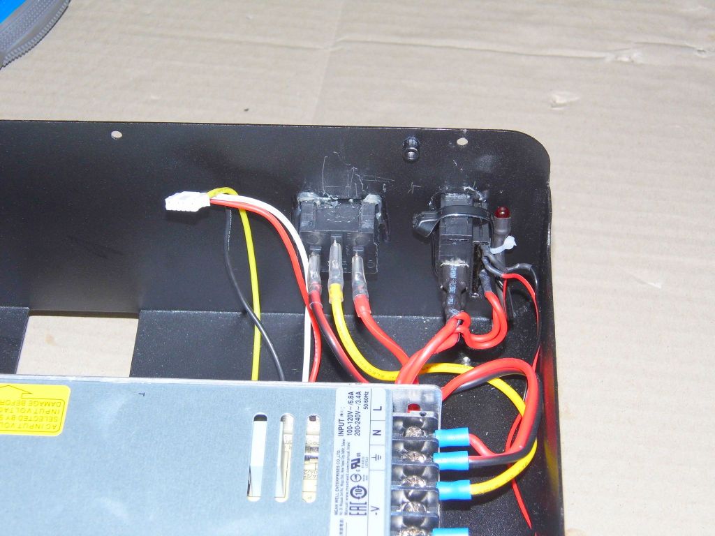
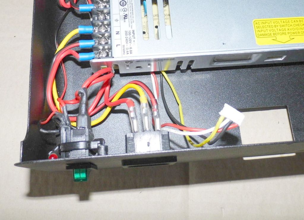
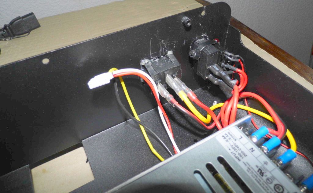
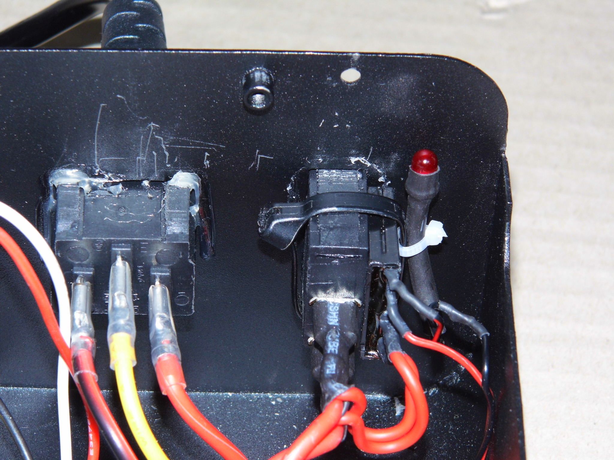
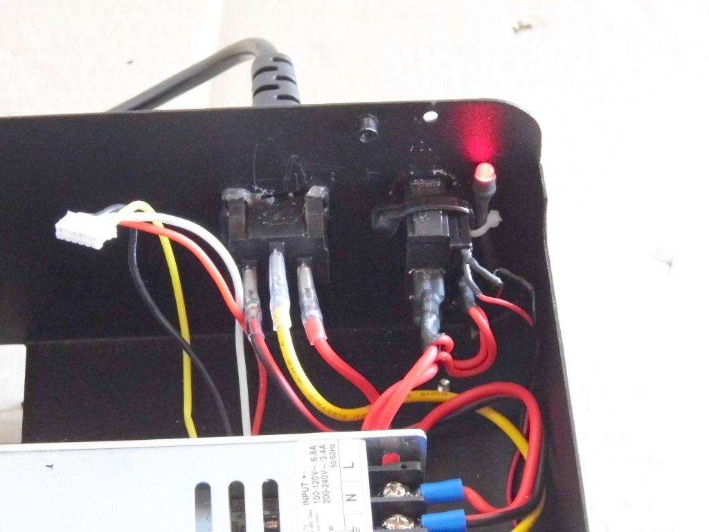
After setting up the circuit, mounting and wiring, check the function again.
Do the third test
For this test, the A5 does not need to be assembled. It can stay open.
- Insert mains plug.
- Power on the printer. Hold down the momentary switch until the beep is over.
- The red LED at the solid state relay should light up and stay on.
- Unplug the power cord.
Note: You can not turn off the printer using the momentary switch.
Update The MKS TFT28 Firmware
From now on, the A5 can already be turned off by software.
A direct possibility to turn off the 3D printer intelligently is still missing. That will be made up. In order to retrofit this function the firmware of the MKS Touch Display needs an update.
How to update the firmware of the MKS display is described here in WIKI. We do not use the official community firmware because the function needed for this project is not included. It would cause confusion when users who do not know this project are constantly complaining about alleged problems.
The firmware for the MKS Touch Display provided here is based on the current (V3.02) community firmware. You do not lose functionality. One of two engine-off icons, which is duplicated in the community firmware, has been replaced. The firmware now includes a power off function. How everything works will be discussed later. Now the firmware of the MKS Touch display has to be updated.
Download
AETEK Firmware:
20180702-03_aetek_jgaurora_a5_custom_lcd_firmware_v3.02.zip
20180714-02_aetek_jgaurora_a5_custom_lcd_firmware_v3.02.zip Fix Filament Out Detection
After the successful update of the MKS display firmware it should now look like this:
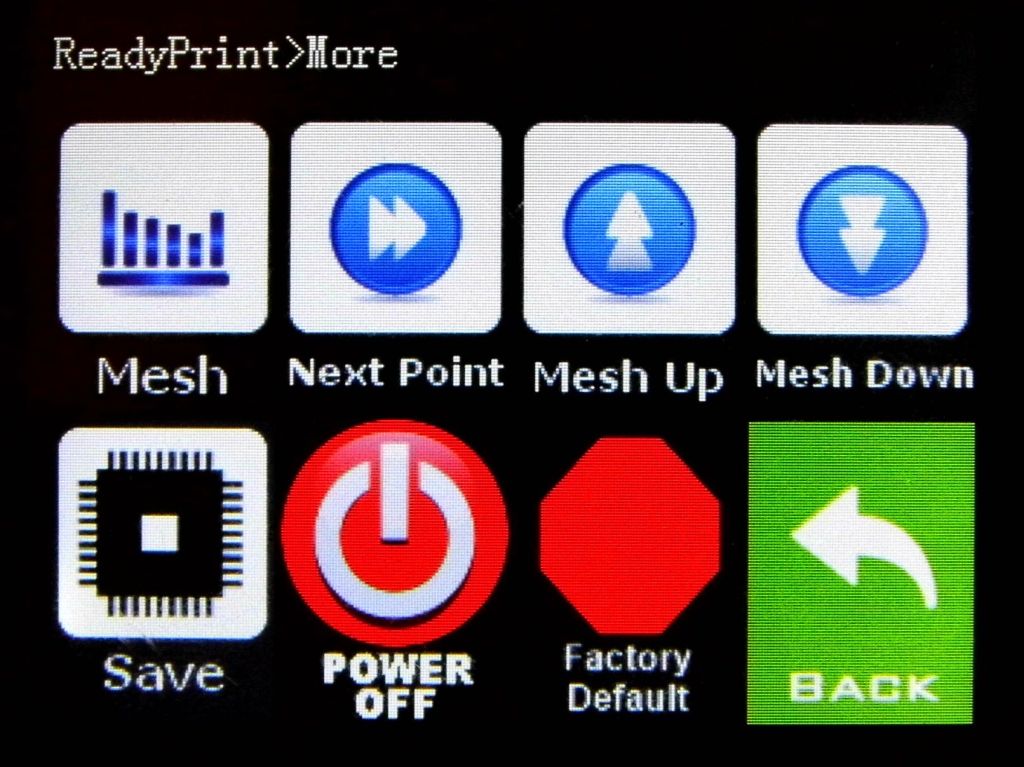
This concludes work on the A5 printer. The A5 can now be completely assembled. 
Use New Functions
The new features can be used in two ways.
- Operation using the MKS Touch Display
- Operation via software (GCODES)
Operation using the MKS Touch Display
The purpose of the effort is computerized power off.
As mentioned in the beginning, it makes no sense to switch off the A5 immediately after touching the switch-off icon. The 3D printer should only be disconnected from the mains if the hot end temperature is not more than 45 ° C. In general, the hot end will initially have a much higher temperature after printing. The normal operating temperature when printing is significantly higher than 45 ° C
The A5 only turns off when it receives a command to do so. If you touch the Power Off Icon on the MKS Touch Display, the A5 waits until the above condition is fulfilled and then switches itself off. This indicates a certain time (usually in minutes range). Therefore, do not expect any direct response from touching the power off icon.
It looks like nothing is happening, but then the 3D printer turns itself off.
The MKS Display Mainboard sends GCODES to the MKS GEN_L 1.0 mainboard. These commands are part of the Marlin firmware and will be explained later. For now I would like to point out a peculiarity when using the power off icon on the MKS display.
If the printer is cold and you touch the power off icon, then you would think that the A5 would now switch off immediately. It is different. The reason for this is the way the GCODE works. The room temperature is hopefully below 45 ° C, for example 25 ° C. Then, when you touch the Power Off Icon, the Hot End heats up to 50 ° C (because of over shoot) and then waits until the Hot End temperature drops to 45 ° C. Only then does the A5 turn off.
While the GCODE is waiting for the 45 ° C to be reached, you can change the display content via the “Back” → “Heat” icon. The current hot-end temperature will be displayed. Marlin includes a buffer for several GCODE commands. After touching the Power Off icon you should not start many actions on the MKS display, otherwise the command to switch off in the buffer could be overwritten. To be sure, you can touch the Power Off Icon again. The power down command is then sent again to Marlin.
Note: If the room temperature is above 44°C, the A5 will never turn off after touching the Power Off Icon.
Summary:
- Switching off is not immediate, but always time-delayed.
- With the “BACK” → “Heat” icon, the current hot-end temperature can be displayed without affecting the switch-off command.
Operation via software (GCODES)
GCODES can be sent directly to the A5 via USB, e.g. Pronterface.
There is also the option to send stored GCODES from a storage device, such as USB stick or SD card.
Which GCODES are of interest for this project?
Source: http://marlinfw.org
M81 - Power Off
Turn off the main power supply. This also shut down the electronics.
Usage: M81
Attention! This command immediately turns off the A5 without waiting for the hot end to cool down.
M85 - Inactivity Shutdown
Use this command to set a maximum period of time for the machine to be inactive (without moves). If the machine is idle for longer than the set period, the firmware will shut everything down and halt the machine.
Usage: M85 S<seconds>
Example: Turn off the A5 after 30 minutes without moving axles
M85 S1800
M109 - Wait for Hotend Temperature
This command sets the hot end temperature and waits for the target temperature to be reached before proceeding. If the temperature is set with R then M109 will also wait for the temperature to go down.
Usage: M109 R<temp>
Example: Wait for a Hot End temperature of 45°C
M109 R45
Application proposals
Every modern slicer program, such as Simplyfy 3D, Cura, Slic3R, etc., has the ability to define a START and END GCODE block. Among other options you can also enter commands for the control of the power supply.
Example: Simplyfy 3D
;STARTING GCODE START --- Simplyfy 3D ----------------------------------------------
M85 S2700		;Power OFF Machine if no movement for 45 minutes.
M140 S[bed1_temperature];Set Bed Temperature + Continue
M109 S120 		;Prepare Hotend for Homing Z. Set Hotend Temp 120C + WAIT
G28 		        ;Home X Y Z Axis\\
G1 Z100 F5000	        ;Lift Z to clean the Nozzle
M190 S[bed1_temperature];Set Bed Temperature + Wait
G1 Z10 F5000		;Z down to 10mm
M109 S190 		;Set Hotend Temperature + Wait
G92 E0 		        ;Reset Extruder
M109 S180 B250 F1 	;Autotemp on 180...250C
;STARTING GCODE END ----------------------------------------------------------------
Power OFF Machine if no movement for 45 minutes: Normally, this case will not occur because the axes are constantly in motion during printing. If the user stops the printer but forgets to turn it off, the A5 will turn itself off after 45 minutes to save energy.
;ENDING GCODE START -----------------------------------------------------------------
G92 E0 			        ;Reset Extruder
G1 X0 Y300 Z320 E-3 F4000	;Quick move Nozzle away while retracting 3mm Filament
M104 S0			        ;Turn hotend off
M140 S0 			;Turn heatbed off
M109 R45 			;Cooldown and wait to reach 45C
M84 			        ;Disable steppers
M81 			        ;Power off
;ENDING GCODE END -------------------------------------------------------------------
At the end of the printing process, the 3D printer waits until the hot end has cooled to 45°C and then shuts itself off.
Status: 5. July 2018: Documentation complete


