Table of Contents
This guide will only work on the 1.1.9 Marlin firmware for the JG A5, which is in beta and may have extra bugs.
A 1.1.8 version may come out if someone else is willing to do one on the wiki however I don't use 1.1.8
Silent Stepper Driver TMC2130

Page format: AETEK
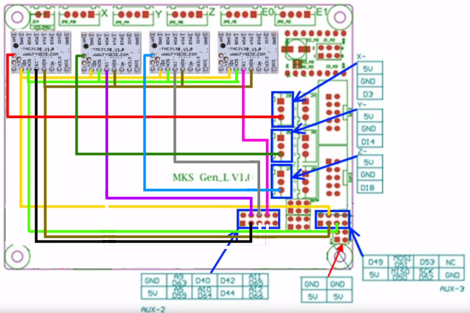
Original wiring diagram: DaHai
Author: Red_M
The changes shown here require knowledge in the field of Arduino IDE, Marlin and electrical engineering and can overwhelm normal users. Also, I would like to point out possible dangers that exist in certain interventions. All adjustments have been checked for function.
Difficulty: Advanced
Why someone would do this
Silent motors, sensor-less homing and higher voltage than the TMC2208s.
Note:
If you want to do this mod, you MUST do both the software changes and the hardware changes.
I HIGHLY recommend the SPI mode and that you purchase the V1.1 instead of the V1.0 for the basic fact of a few extra dollars and much less work.
Required Electrical Parts
- Active Cooling Fan Solution*
- Some cable and heat shrink
* Active Cooling Fan Solution
I recommend using active cooling for the MKS GEN_L mainboard. I have a 80mm 24V fan with an 3D-printed adapter from Thingiverse (only top part) connected directly to the power supply via a Zener diode. The motherboard fan is so quiet that I do not hear it. That's why it runs as long as the A5 is powered. I will not describe the cooling system in this manual. If questions arise I can be contacted via the forum.
Installation
Please first pull the A5 mains plug
Before you install the TMC2130 module into the MKS GEN_L motherboard you should create your cables as per the wiring diagram below and confirm that your drivers have the SPI and other settings correct. I am unsure where exactly the Z and extruder CS pin should go as I didn't have the extra drivers for those axis and DaiHai's wiring diagram on his video was incorrect as I would get readings from the drivers that would be FF:FF:FF:FF meaning that the pin wasn't seeing any data come back from the driver. I got this wiring by trial and error testing. If you don't have the printer erroring on you trying to connect to it then you have the correct pins. If you are trying to get the Z and extruder to be on TMC2130s then I would suggest once you can connect to it, confirming the right pins are plugged into the right connectors by removing them and making sure the one you removed is the one erroring with an overtemp error once you try to connect to the printer again.
If you Upgrade from the factory drivers (A4988) then leave the MS1, MS2 and MS3 jumpers (under the driver modules) plugged in as it is.
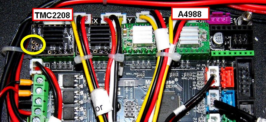
When inserting the modules into the sockets, it must be noted that the mounting direction is different as with the A4988 driver (see photos).

Pictured is the TMC2208, not the TMC2130!
How to set the stepper motor current

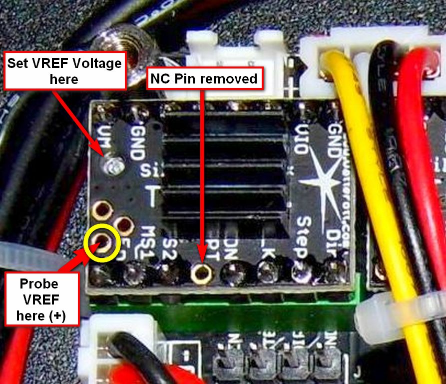
Pictured is the TMC2208, not the TMC2130!
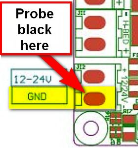
Get the GND (minus) from the MKS GEN_L Mainboard supply input (black wire).

IMPORTANT POINTS:
- When measuring Vref on the TMC2130, you need to measure the voltage from the Vref hole on the V1.0 and the poteniometer on the V1.1, (see photo) to ground.
- Unlike the A4988 stock drivers, the printer power supply must be ON to tune the TMC2130 stepper drivers.
- I HIGHLY RECOMMEND YOU KEEP ALL HANDS AWAY FROM THE BACK OF THE PRINTER SO YOU STAY AWAY FROM THE POWER SUPPLY!
The voltages below are suggested for TMC2XXX stepper drivers (this includes the TMC2130) only:
Axis = Vref
X = 0.85V
Y = 1.25V
Z = 0.85V
E = 1.00V
This concludes work on the A5 hardware for this project. In order for the drivers to work, the Marlin firmware has to be adjusted.
Customize the Marlin firmware
Use TMC2130 for X & Y Axis, the rest stay stock drivers A4988.
The TMC2130 needs a reverse drive on the DIR signal like the A4988.
This can be adjusted in the firmware.
Otherwise the motors will run in the wrong direction.
So we need to change the settings for the X & Y Axis.
In the Arduino IDE open the A5 Custom Community Firmware (see article here in WIKI).
The following adjustments are made in the “Configuration.h” file:
Replace this original code block…
#define INVERT_X_DIR true
#define INVERT_Y_DIR false
…with this customized code:
#define INVERT_X_DIR false
#define INVERT_Y_DIR true
Replace this original code block…
#define X_DRIVER_TYPE  A4988
#define Y_DRIVER_TYPE  A4988
#define Z_DRIVER_TYPE  A4988
…with this customized code:
#define X_DRIVER_TYPE  TMC2130
#define Y_DRIVER_TYPE  TMC2130
#define Z_DRIVER_TYPE  A4988
Make sure you install the TMC2130 Arduino library or you will get compiler errors about missing files. If you want to do the Z and extruder axis as well, make sure you invert the INVERT_Z_DIR and INVERT_E_DIR true/false as well as replace the Z_DRIVER_TYPE and E_DRIVER_TYPE with TMC2130 so that your firmware will use these drivers properly.
The following adjustments are made in the “Configuration_adv.h” file:
Replace this original code block…
//#define MONITOR_DRIVER_STATUS
…with this customized code:
#define MONITOR_DRIVER_STATUS
Replace this original code block…
//#define STEALTHCHOP
…with this customized code:
#define STEALTHCHOP
Replace this original code block…
//#define SENSORLESS_HOMING // TMC2130 only
…with this customized code:
#define SENSORLESS_HOMING // TMC2130 only
Replace this original code block…
//#define TMC_DEBUG
…with this customized code:
#define TMC_DEBUG
The following adjustments are made in the “pins_RAMPS.h” file:
Replace this original code block…
#define X_STEP_PIN         54
#define X_DIR_PIN          55
#define X_ENABLE_PIN       38
#ifndef X_CS_PIN
  #define X_CS_PIN         53
#endif

#define Y_STEP_PIN         60
#define Y_DIR_PIN          61
#define Y_ENABLE_PIN       56
#ifndef Y_CS_PIN
  #define Y_CS_PIN         49
#endif
…with this customized code:
#define X_STEP_PIN         54
#define X_DIR_PIN          55
#define X_ENABLE_PIN       38
#ifndef X_CS_PIN
  #define X_CS_PIN         64 // default 53
#endif

#define Y_STEP_PIN         60
#define Y_DIR_PIN          61
#define Y_ENABLE_PIN       56
#ifndef Y_CS_PIN
  #define Y_CS_PIN         44 // default 49
#endif
If you are intending to also use the Z axis and/or extruder, you will need to assign them pins and make sure you plug the CS wire from the driver into the corresponding pin.
Make sure you install the TMC2130 Arduino library or you will get compiler errors about missing files.
Then upload the changed firmware to the A5 (instructions here in the WIKI).
The 3D printer can now be reassembled.
Check The Proper Function
- Insert mains plug.
- Power on the printer
- Use the Touch Display (Move) or a computer hooked up to the printer to move and check that the X and Y axes are moving in the right direction.
Make sure your X and Y (and Z if you also have the extra driver installed and wired) are going to correct way otherwise you'll need to make sure you did all the changes to the firmware.


